Hardware – Equalization and Pre-emphasis
 Before we look at equalization and pre-emphasis, we should examine some fundamentals of waves and signals. A perfect square wave is a really useful way of representing a waveform in the time-domain, but it’s not the only way of looking at the signal.The name ‘time-domain’ may be new but the view is familiar to us all, you have amplitude on the vertical axis and time you have time on the horizontal scale.
Ideal square waves need infinite bandwidth
The square wave is easy to understand, but unfortunately the ‘perfect’ square wave is a purely theoretical construct. A square wave is actually constructed of many sine waves of different frequencies and amplitudes added together [1]. The fundamental frequency of the signal (e.g. 10Khz) is a sine wave and has the highest amplitude. However there are other many other frequencies called harmonics, which must be successfully received and added to the fundamental signal to ‘square out’ the waveform. To view these signals we need to switch to a new view, the ‘frequency-domain’. The awesome animation below from Wikipedia shows both a time and frequency domain view of a square wave. As more harmonics are added to the frequency-domain, the time-domain signal takes more of a square shape.

So…what’s the problem?
When high-speed signals are received, the shape of the wave is often badly distorted when compared with the transmitted waveform. If the issue was simply attenuation of the the signal, the received signal would have the same shape, just with a lower amplitude. But the received signals that we saw in the eye-diagram post weren’t perfectly square and didn’t show instantaneous transitions from one to zero and vice versa. Instead they are rounded out and stretched.
Why is this happening? We now know that a single square wave is composed of numerous sine waves of different frequencies of different amplitudes. Unfortunately the communications channel (think circuit board and links) doesn’t treat all of these frequencies equally. The channel attenuates some frequencies more than others and this leads to signal distortion at the receiver.
Receive equalization (EQ)
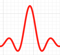
The diagram below is a frequency-domain view of a signal and it’s harmonics. This is a Sinc function [2]. We can see below that the transmitted (Tx) signal in red and the shape of the signal when it is received (Rx) in blue.
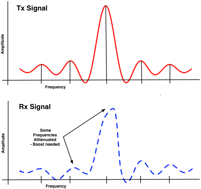
The key point to be made here is that for a given signal, only certain frequencies are attenuated by the channel and at different levels. Equalizers are capable of identifying and amplifying only these particular frequencies and thus restore the shape of the original signal. Once the waveform is fixed in the frequency domain, you’ll see the benefits in a more square-shaped wave in the time-domain.
The electronic design engineer can simulate and measure the response of the signal, then tune the equalizer to boost the right frequencies at the right power levels. There are much more advanced techniques and dynamic equalizers which can measure and dynamically adapt to the changing frequency response of the channel, but that’s for another day.
Pre-emphasis
Ideally you’d have an EQ circuit at both ends of a communications channel. However when the SFP+transceiver was designed you recall that they removed all signal conditioning circuits from the SFP+ transceiver. Without any intervention, the signal from the ASIC would already be badly degraded by the channel before it was translated into an optical signal and sent to the peer network device.
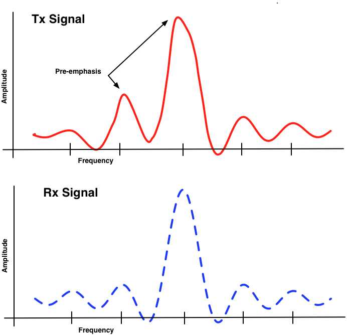
If you already know how the channel is going to attenuate certain frequencies then you can boost those frequencies before you transmit the signal. This is pre-emphasis. I love the idea of knowingly distorting the signal, knowing that the channel will do it’s worst, then still end up with a nice clean signal. Have a look at the diagrams below.
Sherpa Summary
- A square wave is actually composed of a set of sine waves of different frequencies, called harmonics, superimposed on each other.
- You would need infinite bandwidth to transmit all harmonics required to build a perfect square wave, but just a few harmonics will suffice.
- The communications channels affects each of these component frequencies in different ways, leading to distortion of the square wave we see in the time-domain.
- Electronic engineers can model the channel and figure out how it will behave.
- An equalizer is capable of identifying these component frequencies, and applying the right amplification to restore the shape of the square wave.
- Pre-emphasis does this in reverse, by pre-boosting the susceptible frequencies knowing that the channel will attenuate them, bringing them back to ‘normal’ levels.
Footnotes
[1] – If you want to dig deeper on the transformation of the signal from the time-domain to the frequency domain, check out the Fourier Transform
[2] – If it seems familiar, it’s used in the Broadcom logo
3 thoughts on “Hardware – Equalization and Pre-emphasis”
Made me remember my signal processing classes =)
Hey Guilherme,
Yeah, I remember sitting through a few of those classes also. I felt like I understood it one week, but then the torrent of formulae arrived the next week and overwhelmed me :-).
/John H